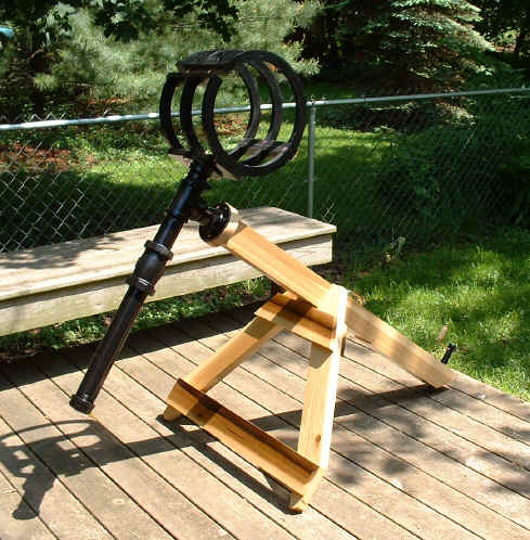
Portable Mount
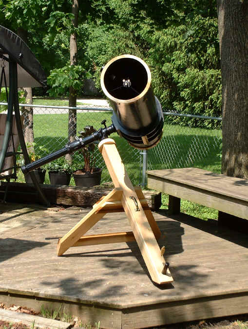
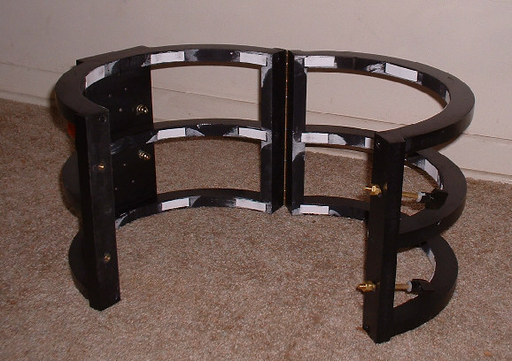
This is a simple variation of the German Equatorial Mount. It uses galvanized pipe fittings, namely a T-fitting, two floor flanges, two close nipples, and a length of pipe for the counterweight. It's important to understand that most pipe and fittings are of the National Pipe Tapered variety. Meaning, the nipples will thread in only so far before they bind. I searched high and low for National Pipe Straight fittings but had no luck. I'm sure you could find them on the web but I would think the shipping would be very expensive. Also, I used Poplar for my mount. It's strong but lightweight and beautiful when finished. However, it does flex a bit under the weight of the OTA (only visible at the eyepiece with extreme magnification) so I would suggest Oak or some other "stiff" hardwood.My solution to the "tapered nipple dilemma" was to use valve-grinding compound on the threads. By doing this I was able to work the nipples in-and-out of the T-fittings, effectively cutting the threads deeper until they engaged to the very end of the taper (well, pretty close anyway). This not only made the bearing surfaces more stable but also gave me more threads on which to apply pressure with the braking system described below. Just be sure and wash off all the compound before proceeding. Note: In order to cut deeper threads, I put the T-fitting in a vise and mounted a long hardwood board to the nipple for leverage. Now with the valve-grinding compound on the threads, it's a simple matter of swinging the board back and forth. You're trying the deepen the thread engagement so try to push it a little farther at the end of each swing. Please make sure you have stable footing, if the T-fitting pops out of the vise...well you get what I mean :-) I won't go into great detail about the construction of this mount. However, the same mount can be found in Making and Enjoying Telescopes by Robert Miller & Kenneth Wilson. This particular support was designed by Dr. Allan Saaf, a contributor to this book. Notice, I used poplar for the OTA end rings (as seen in the bottom photo) and poplar for the mount to match. Update: The aforementioned book is now out of print. However, I did happen upon it at my local public library. If your library doesn't have it, they may be able to borrow from another library in their system.
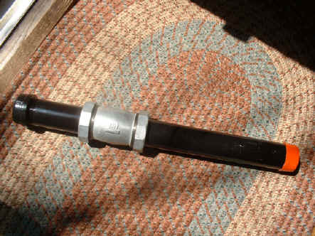
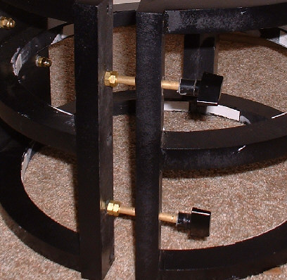
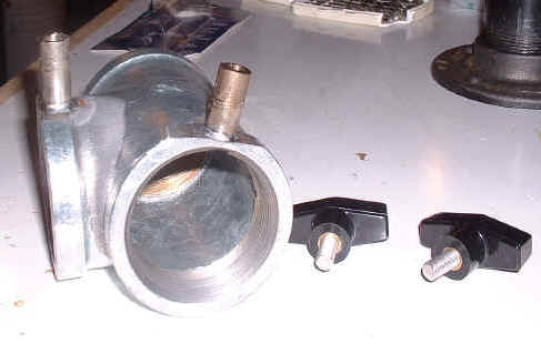
Something I am proud of, however, is what I call the "floating brakes" used in the R.A. and declination axes.
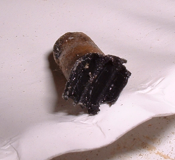
Note: all pipe and fittings are of the 2" galvanized variety. Take care when sanding or grinding galvanized pipe, as the zinc can be toxic. Always use a respirator when performing these functions. The process begins by grinding two "flats" on the "T" fitting, one for each bearing. Drill a rather large hole, I think these were 5/16", and tap to accept the proper size bolt. It is important that these holes are drilled as close to the ends of the fitting as possible. You want to apply pressure to four or five threads. After cutting the heads off the bolts and trimming the threads down so they won't protrude into the fitting, I drilled holes lengthwise through the bolts and tapped them to accept a 5/16-fine thread, hence making a longer shaft for the brakes. When this was complete, I screwed these shafts into the holes I drilled (and tapped) into the T-fitting and soldered them in place with silver solder. Note: don't use stainless steel for the shafts, it is difficult to drill and impossible to tap. Besides, you're going to paint all this anyway, right? Finally, I purchased a couple handles at my local hardware store and fitted them with 5/16 fine threaded rod, pictured above. Snag yourself a couple nylon bushings, small enough to slide easily into the shafts and of the proper length, and grease them up with whatever you are lubricating your bearings with. With your R.A. and declination bearings in place, slide the bushings into the shafts and thread your handles in after. Make sure your bushings are long enough that they won't bind but short enough that the handles will thread in four or five turns. Note: when tapping the shafts, I only tapped about halfway down. You don't want your bushings sliding up and down against threads, it would wear them quickly I would think. Update: Nylon bushings aren't the best idea for the breaking surfaces. They are basically plastic tubes with an inside diameter a bit small that the outside diameter of the 5/16" fine threaded rod. While I was applying pressure on the brake with the 1/4-20 threaded rod handle, the bushing opened up and the threaded rod entered and spread the bushing. This caused the break to seize and jam against the inside of the shaft. Tomorrow I'm going to experiment with other materials. I'm thinking oak dowel might do the job. It comes in an assortment of sizes, it's strong, and should take threads well (I cut threads into oak for my spider/secondary holder adjustment screws). I'll post the results when I know them. Here's a pic of the failed nylon bushing breaking surface. What you can't see in the photo is where the threaded rod entered the back of the tube and cracked it, causing it to spread and jam inside the break housing.
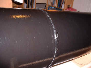
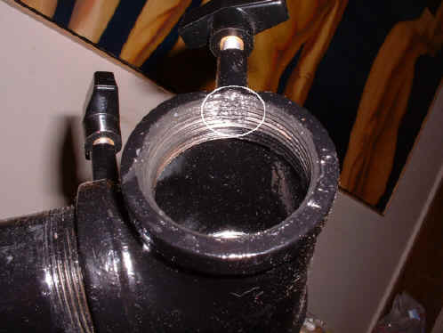
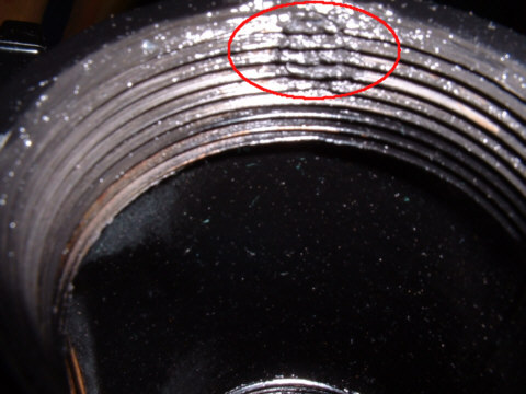
Update: Wood, hard or soft, isn't a good idea for the braking surfaces after all. The wood swells and jams inside the shaft. Now I'm thinking teflon! Another Update: I still haven't found the "perfect" material for the brake pads. Seems that the OTA may be too heavy for the brake to really lock-down. It works very well since I began using solid nylon "rod" rather than bushings but it's not perfect. However, if you're just beginning to fashion your own, consider making the entire braking system larger, 3/8" or possibly even 1/2" if you have the room and it doesn't add too much excess weight. Just make sure the nipple's threads enter the T-fitting past the inner dimension of your brake pads. As I mentioned above, tapered pipe threads will only thread in so far before jamming. Once the bearings are completely assembled and attached to the polar axis, slowly tighten the brakes. As you tighten, work the bearings back and forth. Tighten the brakes a little more and continue rotating the bearings. What we are doing here is cutting threads into the ends of the bushings, exactly matching those found on the inside of the T-fitting. I found that the bushings actually mashed-up against the bearing, giving the break a larger footprint than the bushing's outside diameter. Here is the finished assembly with the break surface circled in white...
...and here is a magnification of the same break surface. Notice how the nylon bushing "squished" into the entire recessed area immediately under the end of the fabricated shaft. The resulting threads in the nylon mesh nicely with the T-fitting threads.
Note: Once a planet or other high-magnification object is centered, tightening the declination axis does move the image a bit. I'm not sure how to overcome this, if it's even possible. It appears to be caused by the slop in the T-fitting and nipple threads. Update: I have been searching for the best grease to use on the nipple threads. Currently I am using white lithium in stick form, kind of like a large crayon. However, I think I would like to try that sticky goop that every telescope owner hates. It is used on cheap focusers in order for the mechanism to slide smoothly AND to take up slop. I think it would work well here..
Now, for the counterweight: I began by filling the capped pipe with molten lead (also very toxic!) until I reached a weight comparable to, but just under, the weight of the OTA. As you can see in the photo, I also added a 2" compression fitting as an adjustable counterweight, allowing for varying sizes of eyepieces. This was necessitated by the fact that I use both 1.25" and 2" optics in my scope. The fitting was a bit pricey, but I just couldn't pass this up, and here's why...
Begin by removing the two caps from the fitting and stretching the rubber seals, hand strength is more than enough to accomplish this task. This allows the fitting to slide easily up and down the pipe. Reassemble the fitting, slide it onto the pipe and make sure it slides freely before the caps are tightened down. Now, it's a simple matter of adjusting the sliding compression-fitting to the necessary point on the counterweight and tightening one of the caps to hold it in place. Note how the rubber seals keep the fitting from marring your paint job, this was an added bonus. Update: Stretching the rubber seals is only a temporary solution (apparently), they tend to shrink back to their original size and become too tight on the pipe. I solved this by inserting a drum sander into my drill press and sanding the interior surfaces of the seals until they slid easily up and down the pipe. Also, I discarded the two metallic rings as these tended to scratch the paint-job. The two threaded caps are more than enough to tighten the seals, and hence the fitting, onto the pipe. IF you don't have a drill press, you'll have to improvise, but the rubber seems to sand pretty well. Just don't inhale the dust. Take note, in the photo below, of the carrying handle mounted to the polar axis. This has considerably simplified assembly in the field. Also, the completed scope was front heavy (OTA side) so I had to rout out a cavity in the underneath of the polar axis. Once routed, I filled the cavity with molten lead (about 15 lbs. of the stuff) and that seemed to do the trick. I capped it with a thin, hmmm...about 1/4", plank of poplar and you would never know the difference.
Update: The OTA "cradle" which holds the scope was constructed out of MDF (my budget had run out by this point). I would urge you to build yours out of hardwood, oak for example, as this should make for a stiffer mount. The MDF flexes a bit and makes for bouncy images at very high magnifications.
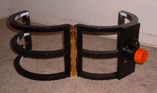
This is the cradle which holds the scope to the mount via a floor flange which pivots in the T-fitting. I used a brass piano hinge (sometimes called a continuous hinge) at the pivot point for strength. Notice that I kept the orange thread caps which came with the pipe and use them for protecting the threads when not in use.
If you have ever used an equatorial mount, you know how difficult it can be to reach the focuser at times. I wanted to save myself some back pain in the field so I designed my cradle to allow the OTA to spin within the cradle. I attached an embroidery hoop the the OTA with wood glue as seen in the picture below. Be sure to place the OTA in the cradle to find the center of balance before gluing the hoop in place.
Because I tighten the cradle only enough to stabilize the OTA, this hoop keeps the scope from sliding out.
Here is a picture of the clamping mechanism used. They are quite simply brass bolts (no heads and threaded both ends) threaded into plastic knobs purchased at the hardware store. The two nuts allow for adjustment of the amount of clamping pressure applied to the OTA. The other side of the cradle opening was drilled and fitted with brass threaded inserts to accept the bolts.
Finally, I added thin strips of melamine to the inside surfaces of the cradle using double-stick tape (photo below). A good coat of car wax on the OTA and the melamine and the scope turns easily inside the cradle, making for a much more pleasurable (and pain-free) viewing experience.
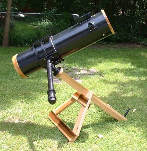
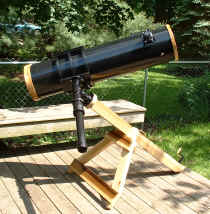
The completed telescope; it was six months in the making but was worth the trip!
Clear skies, -Mac
|
 .
.